Hoses and its processing
Hoses:
Most hoses are
made up of three elements: (1) a tube, (2) reinforcement, and (3) an outer
cover.
1. Tube
2. Reinforcement
3. Outer cover


Each of these
components is usually adhered to the adjacent component by the bonding agents
or thin layer of specially designed rubber.
Tube:
The tube is
the inner most rubber or plastic element of the hose.The tube may be placed over reinforcing elements.
For suitable serive, the tube must be resistant to the materials it is intended
to convey. The Characteristics of the rubber or plastic compound from which
the tube is made and the thickness of
the tube are based on the service for which the hose is designed.
Reinforcement:
Reinforcement
can be textile, plastic or metal alone or in combination, built into the body
of the hose to withstand internal pressures, external forces or a combination
of both .The type and amount of reinforcing material used depends on the
methods of manufacture and on the service requirements.
Cover
The cover is the outer element and can
be made. The prime function of the cover
is to protect the reinforcement form
damage and the environment in which the hose will be used, Covers are designed
for specific applications and can be made to be resistance to oils, acids,
abrasion, flexing, sunlight, ozone, etc.
Manufacturing Materials:
Rubber: To provide a wide range of
physical properties for specific service
needs, elastomers are mixed with various chemicals.
Plastics Materials Used In
hose:
ASTM Designation Common Name
1.PA Nylon
2.PE Polyethylene
3.PVC Polyvinyl chloride
4.Polyester
5. Thermoplastic
Rubber
6.Fluoropolymer(PTFE)
.
Fibres Materials Used in Hose
1.
Aramid- para Aramid
2. Aramid-
Meta Aramid
3. Cotton-
Natural cellulose
4. Glass- Glass
5. Nylon-
Polyamide
6. Polyester- Polyester
7. PVA – Polyvinyl alcohol
8. Rayon- Regenerated cellulose
Fabrics:
Textile fabrics used as reinforcement in
hose construction provide the strength to achieve the desired resistance to
internal pressure or to provide resistance to collapse or both. The
properties of a fabric depend on the
construction and the material from which the yarn is made and on type of weave
used. One common hose fabric is woven from warp yarns which run length wise and
filling yarns, which run cross wise. Usually they are woven at right angles to
each other. The most common weave is known as plain weave.
Leno Weave
Leno Weave is used mainly where the fabric must be distorted in
the hose as in certain types of curved hose. Leno also provides a means for
better adhesion than other patterns. Woven cord is a special type of hose
reinforcement. The warp cords are strong while the filling yarn is very fine
and merely hold the cords in position. This is often called tire cord because
this type of construction is commonly used in reinforcing tires. Woven cord
provides strength in one direction only. When woven cord is used a minimum of
two layers are applied in alternate directions. To adhere to the tube and cover
of the hose,the fabic must be rubberized. The fabric is either fabricated or
coated with a thin layer of rubber. Before rubberizing some fabrics are treated with liquid
adhesive.
YARNS:
Yarns are used in hose for reinforcement of the tube material to
provide the strength to achieve the desired resistance to internal pressure or
to provide resistance to collapse, or both. The basic yarn properties required
for hose reinforcement are : adequate strength, acceptable heat
resistance,dynamic fatigue resistance and satisfactory process ability for the
various methods of reinforcing hose. Other special properties such as
stiffness, adhesion, conductivity, etc. may be developed depending upon the
specific hose application. Yarn is available in two basic forms; Staple(
sometimes referred to as spun yarn) and filament.
Staple:
Staple yarn is
made by twiating bundles of short fibers to form a continuous yarn. The staple
obtains its strength from the binding effect of the twist imparted to the individual fibers. The base staple yarn
is called a singles. It is made from fiber bundles twisted together in one
direction to form a single strand.
If two or more single yarn are twisted
together usually in a direction opposite that of the single yarn
the result is a plied yarn. Two or more
plied yarns may be twisted to form a cable cord. The strength, elongation and thickness of yarn are a function of the
twist level and the number of fibers in the bundle.
Staple yarns may be made from natural or synthetic fibers or a blend
of the two. The cotton count system is normally used to designate staple yarn size.
The number of “hanks” in one pound is the yarn number. A cotton
hank is 840 yards. Therefore, a 2’s staple
yarn contains approximately 1680 yards in one pound. The cotton count
system is an inverse
measure of the linear density of the
yarn, i.e., as the yarn number increases the yarn size is decreased.
Filament Yarns
Filament yarn is produced by extruding synthetic material through a spinnerette containing hundreds
of orifices. The monofilaments form each of the orifices are brought together
to form a multifilament yarn.
Filament yarns have higher tenacity (
Strength per unit of weight- grams per denier), in the range of 2 to 3 times that of staple yarn on the same
material type and size)
Yarn size is normally designated using
the denier system(weight in grams of 1000 meters of yarn) is alos widely used.
Both are direct yarn measurements. i.e, as
the number increases the yarn increases.
WIRES:
Reinforcing wire is used in a wide
variety of hydraulic and industrial hose, primarily where textiles alone do no
satisfy the special engineering requirements or the service conditions for
which the hose is designed.
Steel Wire:
Steel wire has strength, high modulus
for dimensional stability, fatigue resistance and low cost and is the major
reinforcement used in high pressure hose and in most suction hose.
Steel Wire (High
Tensile Low Carbon)
Small diameter high tensile steel wire
is most commonly used for reinforcement in braided or spiral-wound hose for
high pressures and high temperature applications. The wire normally used ranges
in size from 0.008 inch to 0.037 inch (0.20 mm to 0.94 mm) in diameter.
Flat wire Braid:
This consists of an odd number of steel
wires interwoven to produce a flexible reinforcement. It is used in specialized
type of hose, either by itself of in combination with other shapes of steel wire. Flat braids
of standard sizes are composed of
9,13,17 or 21 strands of wire in an over two under two plain braid pattern.
Wire
cable:
Wire cable consists of multiple strands
of round wire. It provides high bursting strength without undue loss of
flexibility or crush resistance. Sizes range form 0.047 inch to 0.25 inch (1.19 mm to 6.4 mm) in diameter and are made
from high tensile carbon steel wire.
Round Wire
Round is the most commonly used wire shape in hose fabrication. It ranges in size from
0.031 inch to 0.875 inch (0.79 mm to
22.2 mm) in diameter. Round wire is generally made of high tensile carbon
steel.
Rectangular Wire
Rectangular wire is most commonly used
as a helical reinforcement on the interior of rough
bore suction hoses to prevent collapse.
It is sometimes used in the body of the hose.
Occasionally this type of wire is also
used as an external helix embedded in and flush with the
rubber cover to provide protection
against cutting and abrasion and to increase crush
resistance. Rectangular wire is
generally steel, although aluminum may also be used.
Half-Round Wire
Half round
steel wire is used mainly as a protective spiral armor on the exterior of a
hose. It is wound with the flat side against the hose cover to provide maximum
surface contact. It is available in stainless steel or steel with tin coated or
galvanized finishes.
Wire Finishes
Wire finishes for steel wire can be
either one of two types, (1) brass drawn finish, or (2)
coated finish. The most commonly used
finish in the hose industry is brass (drawn finish), or
galvanized (coated finish). Other
finishes include bronze, liquor, and tin. Helical round
wires used as helical wound in the body
of a hose may have a drawn copper finish, or may be
unfinished (bright). Rectangular steel
wires used in the bore of a hose usually have a galvanized
finish.
Alloy and Non-Ferrous
Wires
Under certain
service conditions, carbon steel wire is not suitable. An alloy wire is used
instead. One of the most commonly used is stainless steel which offers
exceptional resistance to corrosion and heat. Where light weight is essential,
alloys of aluminum are used.
Static Wires
Static wires and other conductive
materials are used in hose to prevent static electricity
buildup. Wires can be made from many
metals including copper, steel, monel, aluminum and
tin-coated copper. Static wires may be
solid, stranded, or braided.
Manufacturing Methods
The principal methods used to
manufacture hose will be described and illustrated in this chapter. The
three basic methods: (1) non-mandrel,
(2) flexible mandrel, and (3) rigid mandrel, describe how the various
components of the hose are supported
during processing into a finished product.
THREE BASIC METHODS
OF MAKING
HOSE
Hose is manufactured in the
unvulcanizedstate by forming a cylindrical tube over which areinforcement and
cylindrical cover are applied.n its uncured form, a hose tube will often
needsupport to maintain proper internal diameterID) and dimensional tolerances
while beingprocessed through the various stages ofmanufacture. Thus, the three
basic methods of
making hose have evolved: (1)
non-mandrel, (2)lexible mandrel, and (3) rigid mandrel. Inmethods (2) and (3),
the mandrels are used forsupport and as dimensional control devices for
the hose tube during processing. Then
after thehose building and, if necessary, thevulcanization are complete, the
mandrels areremoved, inspected and recycled.
Non-mandrel Style:
The non
mandrel method of manufacture is generally used for lower working pressure(
less than 500 psi), smaller diameter texile reinforced products not requiring
stringent dimensional tolerance. Typical hose products in this category would
include garden, washing machine inlet and multipurpose air and water styles.
Essentially the non mandrel technique
involves extruding the tube, applying the reinforcing and extruding the cover
in the unsupported mode( without a mandrel). Frequently low pressure air is
used inside the tube for minimal support, Keeping the tube from flattening
during the reinforcing process. In some cases, especially 1 to 2 inch ID, the
tube may be extruded with air injection
along with an internal lubricant to prevent adherence to itself.
The non-mandrel tube extrusion process
can be done continuously, if appropriate
handling equipment is available, thus providing excellent length patterns for
the finished product. In recent years with improvements in die design and
cooling, dimensional control of non mandrel
Rubber tube is approaching that of
flexible mandrel style.
Most smooth bore thermoplastic hoses
are extruded non-mandrel. The higher
rigidity of most thermoplastics eliminates the need for mandrel support. In
addition, with advanced cooling and
dimensional sizing equipment, thermoplastic tube dimensions can be maintained
quite accurately.
Flexible Mandrel
Style
When moderate tube processing support is
needed and more accurate dimensional tolerances are a concern, flexible
mandrels may
be
utilized. These mandrels are rubber or
thermoplastic extrusions, sometimes with
a wire core to minimize distortion. This style process
may be used for mid-range working
pressures (up to 5000 psi) with ID’s of 1/8" to 1-1/2".
Of the three flexible mandrel styles,
solid rubber offers minimal support, while rubber with wire core and
thermoplastic versions provide good dimensional control. In all cases, the
flexible mandrel is removed from the hose with either hydrostatic pressure or
mechanical push/pull after processing. The mandrel is then inspected for
dimensional and cosmetic imperfections, rejoined into a continuous length,
and recycled into the hose making
process. Although the flexible mandrel is continuous, limitations of expulsion
from the finished hose rarely allow hose lengths above 1000 ft. Either textile or wire reinforcements may be
used. Examples of this style product are power
steering, hydraulic, wire braided and
air conditioning hoses.
Rigid Mandrel Style
In larger hose sizes, where flexible
mandrels become quite cumbersome to handle, working
pressures are high, or stringent
dimensional control is required, the rigid mandrel process is
the preferred technique.
This method is used for any rubber hose
larger than 2" ID and for 1/8" to 2" ID constructions that have
higher working pressures, especially wire spiral reinforced products.The rigid mandrels are normally aluminum
or steel. For specialty applications where cleanliness is a necessity, stainless
steel mandrels are used. Because of weight considerations the mandrels are usually
hollow. Mandrel lengths vary from 10 ft. to 400 ft. with 100 ft. to 200 ft. being the most
common. The hose tube may be either extruded on the mandrel, pneumatically pulled onto the mandrel, or wrapped in sheets onto the mandrel. As with the flexible mandrel style, when
the hose manufacturing process is complete, the mandrel is removed and prepared for
recycling.
Manufacturing with rigid mandrels offers
two unique production opportunities.
Rigid mandrels can be (1) rotated on a
stationary horizontal axis, similar to a lathe, so that material can be applied in bias style or
(2) fed horizontally through the tubing, reinforcing and covering operations as the various hose
components are spirally fed onto the mandrel.
The former method is often referred to
as Hand Built hose. The reference of Wrapped Ply hose
can be associated with either method.
Some hand built hoses, depending on the application,
have special ends to accommodate its
attachment to existing flanges in the field.
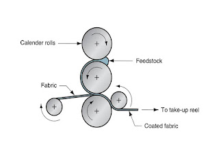
One traditional method of making wrapped
ply hose is on a three roll builder. This machine
consists of three long steel rolls, two
of which are in a fixed parallel position in the same
horizontal plane.
The third or top roll is on pivotal
mounts so that it can be raised or lowered. A mandrel
supported hose tube is placed on the
trough between the two bottom rolls.
Then the top roll is rotated down with
sufficient pressure to cause the mandrel and
tube to rotate. This enables the
reinforcement and cover to be bias wrapped over the tube in
uniform fashion.
.
SPECIALTY METHODS
Although the three basic methods of hose manufacture just discussed encompass the
vast
majority of techniques currently in use,
there are still a variety of specialty methods
that deserve
attention in this synopsis. Most of
these pertain to thermoplastic hose styles.
Thermoplastic Hose
Concepts
Thermoplastic products such as vacuum cleaner hoses, used for very low pressure applications are
often manufactured with blow molded or tape forming techniques.
Blow molded products are shaped into a circumferentially corrugated
profile at the tube
extruder when the thermoplastic material
is still in the molten state. The corrugations provide a
tremendous improvement in product
flexibility and stretch characteristics. The profiling is accomplished by
injecting air into the tube pushing it into a series of metal die blocks
corrugated with the intended profile. As
the tube cools while traveling along the die block track,
the tube becomes permanently corrugated
circumferentially. A similar process,
vacuum
forming, uses the same technique of
corrugated die blocks at the extruder, but instead of
blowing air in the tube, a vacuum is
drawn through the blocks pulling the molten tube into
the corrugations. The appearance of the
final product from each method is quite similar.
However the vacuum forming process
generally yields superior corrugation uniformity.
The corrugated tube from this process
may be the final product or used in conjunction with
other hose components. For instance, for
higher pressure applications an adequate reinforcement
may be applied and then a smooth cover
extrusion. Combinations of rubber and plastic
layers may provide the best appearance
for a specific application.
Tape forming process is a general term
to describe a product composed of a narrow
thermoplastic extruded profile helically
wrapped with sufficient overlap and adequate
bonding to create a continuous cylinder
with hose-like characteristics. The profile can be
varied for best flexibility. Typically
swimming pool hoses are of this construction
Helically applied wire at the
thermoplastic extrusion point offers another product option
that results in good crush resistance
and flexibility.
Low pressure gasoline vapor recovery
hoses may use this design.
Continuous Systems
To minimize handling inventory and cost while maximizing throughput, the continuous
process is common. This process combines
tubing, reinforcing, covering and vulcanization
into a single process. To do this, the
equipment is merely installed in a tandem fashion thereby
enabling the hose material to flow
uninterrupted through each phase. Obviously the system
controls are vitally important to
minimize downtime. Since the line output is generally
limited by the reinforcement unit
capacity, textile spiraling is the common approach. Also,
since the vulcanization portion of the
line is often the most space consuming and expensive,
it is frequently not included. Hoses up
to 2" ID with working-pressures up to 400 psi are the most
probable candidates for this process.
Flexible mandrel or non-mandrel methods can be
accommodated on the continuous process.
PROCESS
CHARACTERISTICS
As previously mentioned, the basic hose
components are the tube, reinforcement,
and
cover. In this section the process
methods for
each of these operations will be
outlined.
TUBING OPERATION
The two common tube manufacturing techniques are extruded and wrapped.
Extruded Tubes
For the tube extrusion process, an
uncured rubber or thermoplastic compound ribbon or
pellets are fed into the extruder,
through the screw or auger with proper temperature controls
and finally forced through a pair of
metal dies, where the cylindrical tube is formed. In the non continuous
process,the tube is then cooled,
lubricated to minimize tackiness and stored in coils on
pans, reels,or rigid mandrel poles.
Dimensional control is critical when the
tube is being formed. Traditional techniques for maintaining dimensions include
die selection, temperature, and line speed adjustments. The
latest innovations include a multi-axis
laser micrometer measuring the tube outer diameter
with feedback to the extruder to provide
size control. Ultrasonic devices, that can measure
tube ID and OD, are also available. important to prevent scorch or partial cure
of
rubber compounds or burning of the thermoplastics
during extrusion and provide
good wall gauge concentricity. The
various temperature zones of the extruder provide for a
profile that can be varied for each type
of compound to help optimize extrusion characteristics. For certain applications, to minimize cost or improve flexibility,
multiple tube layers may be desirable. In these instances, a tandem or co- extrusion
may be preferred. For the tandem method, extruders are installed in series so
one tube may be extruded over the other.
For co extrusions, several extruders are mounted in such a way to feed a
central die-forming point (extruder head)so that the tubing operation is simultaneous.
These extrusion advancements offer a
Good variety of alternatives to use unique polymers or to create hybrid
products of thermoplastic and rubber.
Normally, extrusion is the preferred
method for the tubing process on hoses with ID’s up to
1-1/2" when built on a flexible
mandrel, to 4" for rigid mandrel.
Beyond these dimensions,
wrapped is usually employed. For the
larger diameter non-mandrel extrusions, the tube may
be lubricated inside to prevent compound
tackiness. Also, an air cushion can be used
internally to prevent tube collapse
during
extrusion.
Extruders are often referred to as
crosshead or straight head. If the tube is formed in the same
direction as the extruder’s screw
orientation, it is a straight head design, whereas if there is an
angle between the tube flow and the
screw, it is a crosshead design. Common crosshead designs
are 45° or 90° orientation. Crosshead
designs offer more challenges for the process engineer
or rubber chemists since the abrupt
change in rubber flow direction can induce temperature
and pressure anomalies, especially with sensitive
compounds.
Hot feed and cold feed extruder terminology
is common. In the Hot feed process
the rubber is preheated before it is fed
into the extruder, usually on a two-roll mill. This
technique makes the extrusion easier for
some compounds since there is less rapid temperature
increase in the rubber. However with
high equipment and labor cost, it is almost obsolete
in favor of the cold feed process.
Wrapped Tubes
For the larger diameter rigid mandrel
rubber hose constructions, the wrapped tube process is
utilized. Here, the rubber compound is calendered
to a specific thickness and width,
then spirally wrapped on the rigid
mandrel with sufficient overlap to form the tube. With the
wrapped process, the challenge is to
provide good bonding at the tube overlap area to prevent
tube delamination.
COVERING OPERATION
The covering techniques used for rubber and thermoplastics are synonymous with the
tubing techniques described previously.
In most instances the same equipment is used.
Frequently a hose may have an extruded
tube and a wrapped cover. If extruded, covers must
be applied with a crosshead design to
allow the reinforced uncured tube to be fed properly into
the extruder covering.
REINFORCEMENT
The strength component of the hose, designed to handle the entire pressure load with
appropriate safety factors is the
reinforcement. In most cases it is located between the tube and
cover. Occasionally there are hose
applications not requiring a cover, in which case the
reinforcement also acts as the outer
protective layer.
When multiple plies of reinforcement are
required to meet working pressure performance
levels, typically they are applied one
over the other normally separated with a rubber layer
(friction or jacket) to fill voids,
prevent adjacent reinforcement abrasion, and to maintain
adequate hose component adhesion levels.
Multiple plies may be applied individually or in
a single pass through a multiple deck
unit.
Methods of applying these reinforcements
are braid, spiral, knit, wrap, and woven. Combinations, such as
spiral/knit, are available. Selection of
reinforcing equipment is dependent on pressure
rating, size, fitting requirements,
flexibility, and crush resistance levels.
Braid Reinforcement
Braiding is probably the most common and
traditional method of reinforcing hose. Braiding
machines were available in France and Germany
as early as the middle of the l9th
century for braiding textiles used for
rope and clothing products. The introduction of the first
braiders for the fledgling hose industry
came in America about 1900.
Braiders are described as vertical or horizontal
depending on the direction the tube
progresses through the machine during
braiding. The two major classifications of braiders are
tubular or “maypole” type and rotary
type.
Maypole Type
As the name implies, braid is formed
from multiple carriers each carrying a reinforcement
package traveling in a serpentine
maypole fashion generally with a two over-two under
pattern. The common carrier varieties
available are 20, 24, 36, 48, and 64. They are utilized in
vertical or horizontal, single or
multiple deck arrangements.
Vertical set-ups are normally a maximum
of two decks for convenience and handle nonmandrel or flexible mandrel hoses up to 1- ½ inches
ID .
For vertical braiding,the tube is fed Into
the braider From underneath,
Passing through The center of the unit
where the braid Is applied and then over a rotating capstan wheel designed to
pull the tube through the braider at a specified
rate so the braid is applied at the optimum design angle. For non mandrel style
products an air cushion is often used inside the tube to
prevent collapse at the braid point.
The vertical braider is the most old fashioned style with few recent advancements.
Output speeds are about 30% less than the latest horizontal maypole braider
innovations.
Rotary Type
The term rotary braider applies to units
where the carriers holding the reinforcement
package are fixed on two
counter-rotating decks and do not move in and out in a serpentine path
like the maypole type. The braiding
pattern is achieved by deflecting the reinforcement
strands from the outside deck under and
over two carriers on the inside deck, repeating the
motion continuously during rotation.
Because of the simpler travel of the carriers, output speeds
can be as much as 200% faster than an equivalent
maypole type. Common arrangements are available in 20, 24, 36, 48 carriers,
vertical and horizontal, one-, two- or three-deck setups for both textile and
wire reinforcement.
Spiral Reinforcement
Hose spiral reinforcement equipment
first became available in the 1950’s. Since then, it
has evolved into the most economical and
efficient method of making certain types of
hose. Spiralling is done horizontally
with two opposing decks revolving in opposite directions
each holding clusters of reinforcement
spindles.
Each strand of reinforcement is fed
through an array of tensioning devices to the center point of
the decks where they are applied to the
tube in a parallel array. In all cases, to have a balanced
hose construction capable of minimal
distortion under pressure, the spirals are always in
multiples of two. Because of the minimal number of moving parts, the spiral decks
can
turn at very high rates.
State-of-the-art textile spiral units, available at 2000 rpm are
commonly used in continuous lines where tubing,
reinforcing and covering are all done in
one pass. Textile spiral is well suited
for nonmandrel or flexible mandrel constructions with low to medium pressure
ratings. Wire spiral is most common on rigid mandrels designs up to 2 inch ID
with very high working pressures.
Single or double wire spiral applicators may be used in conjunction with
a textile braid or
spiral to form a “helix wire” in the
hose wall to provide collapse resistance. These are common
for large diameter suction hoses (over
1") or in gasoline pump hose where the “hardwall”
Knit Reinforcement
Rotary knitting machines used for hose reinforcement were first developed in the early
1900’s. Today their use has declined significantly
in favor of textile spiral, but are
still the common method for reinforcing
radiator hose because of its good torsional and
circumferential flexibility needed for
curved hose products.
Knitting can be horizontal or vertical
with textile only. The yarn is fed from cone packages
(usually 4 or 8) through a series of
eyelets through latch-type needles onto the hose.
Although the knitted hose is easily
shapeable for coolant hose applications, it is a very
inefficient reinforcing method
restricted to low pressure applications.
Wrap Reinforcement
Wrap reinforcement is applied spirally
to rigid mandrel hose tube in multiple plies with
the direction of lay reversed with each succeeding
ply. The most common fabric
reinforcement is tire cord, which has
strength only in the cord direction. To compensate for its
uni-directional strength, plies are
usually applied in multiples of two. This may be done
by rotating the mandrel or rotating the reinforcement
around the mandrel as described
previously in the “Three Basic Methods
of Making Hose”. Wrapping is generally done
with rubberized fabric thereby resulting
in hoses in the lower working pressure range. However
for large diameter hoses, generally
above 4", it's the only available technique
When needed to prevent collapse or kinking,
a wire or thermoplastic helix or helixes
are added to the wrapped
construction. These can be a wide
variety of thicknesses, usually
applied at a fairly high helix angle to
oppose inward and outward radial stress, but which do
not add significantly to the hose
strength in the axial direction.
Woven Hose
The reinforcement for woven hose is a seamless, tubular textile jacket woven on a
loom. This produces a strong,
lightweight hose that is flexible for flat storage. Because the
longitudinal warp yarns are parallel to
the axis, woven hose tends to kink more easily than other
hose constructions. Although sometimes
used with a rubber cover for industrial applications,
woven discharge hose finds its greatest
use as a fire hose where lightweight and high strength are of great importance.
Fire hose consists of a tube and
seamless circular woven jacket or jackets, either separate or interwoven. The
tube may consist of a rubber or plastic compound. The tube may be extruded,
wrapped, or built up by depositing multiple layers of
rubber latex. If compounded rubber has been used as a tube,
it may be semi-cured and then backed
with a supplemental layer of rubber. This step is
eliminated in the case of plastic tubes.
The tube is then drawn into the jacket or jackets and,
when made with rubber compounds, it is
cured by internal steam pressure, with the jackets
being the pressure container. Fire hose is normally made without an outer
rubber cover or protection to the outer
jacket. For certain applications, especially in the
chemical industry and at refineries
where damage to the jacket would occur from
aggressive liquids, it is normal to use
either a rubber covered hose or a hose where the outer
jacket has been impregnated with a
rubber type protective coating.
A great deal of rubber covered fire hose
is made by weaving the jackets on a loom. Then
the tube and cover are applied simultaneously
by pulling the jacket through a special cross
head extruder. This extruder forces the compound
through the weave forming a onepiece
tube and cover.
A common loom variety, a Chernack loom, is a four-shuttle circular loom in which every
alternate fill member may be of
different material.
A hose made with this loom normally
would be provided with an inner liner which would be
drawn into the circular woven member simultaneously
with the weaving procedure.
The primary use of a hose from such a
loom is for suction applications. This construction
would normally have two alternate
members of round wire or plastic rods having physical
characteristics which would provide
substantial crush resistance in the hose structure. The other
two would be textile yarn.
VULCANIZATION
TECHNIQUES
Vulcanization (curing) changes the
rubber product from a plastic to elastic material that is
much stronger and rebounds to its original
shape after load deformation. All rubber
products need to go through the “curing”
transformation, the final process, whereas with
thermoplastic products, it is not
required.
Vulcanization is achieved by heating the
rubber products to temperature generally between 280°
F to 400°F. Although pressurized steam
is the traditional method, techniques ranging from hot
air, molten eutectic salts, hot glass
beads, and high frequency microwaves have been used
quite successfully for certain hose
applications. Since the use of steam has become the most
widely used method throughout the rubber
industry, the techniques that will be described
here will be lead sheath, wrap, open,
and curved. All these methods utilize a steam
vulcanizer for curing the rubber.
The lead sheath is applied as a hot
extrusion through a set of dies. Its purpose is to compress the hose components
thereby providing good bonding or homogeneous structure with
adequate concentric dimensions. This
method can be used for non-mandrel or flexible mandrel
constructions. For non-mandrel styles, air or water is
charged inside the hose for support
during vulcanization.
After curing, the lead is stripped from
the hose with a series of knives and melted for recycling. Although old fashioned and energy consuming,
this method is still commonly used for multiple pIy hoses 11/2"
And smaller.However with environmental
concerns of the lead this process is becoming obsolete.
Alternate material approaches to lead
that still utilize an extruded sheath include a variety
of heat stabilized thermoplastics.
Although the compressive characteristics are not nearly as
good as lead, for lighter weight
products, especially single ply, a thermoplastic sheath
cure might be a good alternative to
lead.
Wrap Cure
The wrap cure process uses a closely woven textile fabric tape generally 2" to 4" in width,
wrapped spirally around the uncured hose
and steam vulcanized. This fabric tape, generally
nylon, is overlapped sufficiently that
along with the shrinkage properties of the textile, provide
compaction forces to the hose bonding
the components during cure. The tape is removed
and recycled after cure. The rough
surface of the tape creates a similar rough finish on the
hose. Wrap curing is used for flexible
or rigid mandrel constructions in virtually all sizes.
Open Cure
Open or pan cure is the simplest of
rubber hose vulcanization techniques. Essentially, the
hose is taken from the covering
operation, coiled either on reels or horizontal pans and
placed directly into the vulcanizer.
Obviously, without any protective or compressive sheath
during cure, this process is limited to
products of one or two ply and 1" ID or less, either nonmandrel
or flexible mandrel. If non mandrel a
water or air charge may be used inside the hose for support during cure.
Curved Hose
For certain applications, such as
automotive coolant hose, a curved or shaped configuration
is required for the hose. In these
cases, theuncured hose is cut to the specified length,
installed on a metal mandrel that is the
same shape as the finished part, open steam
vulcanized, and then removed from the mandrel.
Because the hose is cured in this
configuration, it retains the shape of
the mandrel.

Fantastic blog! The data is well written. I wanted to leave a little comment to support you . Wish you best of luck for all your best efforts. Thanks for sharing such an amazing post with us and keep blogging! If you would like to know more about hose hydraulic then please visit our website.
ReplyDeleteIf you have experienced an unexpected loss of water in your home then you may have suffered a lot of loss which may make you think that we should save water so that there is no distress in life and if water is wasted in the house then the house is also damaged. For all these solutions you can contact restassuredrestored company which will help you to water restoration.
ReplyDeleteFantastic blog! The data is well written. I wanted to leave a little comment to support you . Choose Ciao Bella Cleaning for the https://ciaobellacleaning.com.au/.
ReplyDeletegreat blog thanks for sharing
ReplyDeleteSilicone Cables