High pressure hydraulic hose
High Pressure
Hydraulic hose
In recent years hydraulic has grown steadily and
this trends is likely to continue well into the next century. The technological
demands made on hydraulic hose manufactures have also increased and will
intensify further in parallel with
market requirements for high pressure hoses.
Pressure levels available
for high pressure hoses have increased inordinately with improved design and
the wire industry has provided a higher strength product to give designer the necessary
material to facilitate these advances. Larger diameter wires with very high
tensile strengths are now available which have the processing characteristics
necessary for hose manufacture.
Aramid textile fiber
has also played a significant role in allowing
the production of
higher pressure hoses particularly for
the offshore oil industy. Hoses have become slimmer in wall, lighter in weight
and more flexible
thus they are able to work at lower bend radii and with capability and because
of improvements in compound design and the availability of newer elastomers, at
much higher temperatures. The distinction between rubber and plastics has
become quite blurred with some thermoplastics having properties that make them
virtually indistinguishable from traditional vulcanized rubbers and such
material have found a place in the hose manufacturing industry.
Hoses have been
combined with electric cables as an integral product to allow the transmission in
a single flexible conduit of electric power or communication signals and hydraulic pressure.
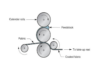
Hoses form 5 to 32 mm
bore are usually made on flexible rubber
or thermoplasic mandrels. The innerliner is crosshead extruded on the lubricated mandrel form a cold feed rubber
extruder. A short freezing section just prior to the braider ensures that the
inner liner is hard enough to withstand the stresses of braiding.
After braiding the
hose is covered on a cold feed crosshead extruder frequently the hose is
branded at this stage immediately downstream of the crosshead antitack is
required is applied and after a period of maturing the hose is either passed
through a lead extruder( where a lead sheath slightly smaller than the outside
diameter of the hose is applied) or wrapped with nylon fabric on an orbital or
concentric wrapping machine. Whether wrapped or leaded the hoses are coiled onto
drums which are placed in an autoclave to effect cure. The time and temperature
of vulcanization depends on several factors such as mandrel types but it is
important in hydraulic hose manufacture
to obtain a tight cure to minimize
compression set, an important property for good end fitting retention. It is also
important property for good end fitting
retention. It is also important to have compound that cure at similar rates to
ensure good bonding between compounds.
After cure and
cooling the lead is stripped off or the wrap is taken off and the mandrel
should be loose inside the vulcanized hose. The mandrel loosens because of the significant thermal expansion differential
between the mandrel ( and the inner liner material) and the metal
reinforcement.
During heating in the autoclave the mandrel and the innerliner compounds swell relative to the wire reinforcement. The inner liner material is forced outward into the braid interstices, and bonding to the wire reinforcement takes place. Upon cooling, the mandrel shrinks back to its original size leaving the inner liner bonded to the wire and a gap develops between the mandrel and the inner liner.
During heating in the autoclave the mandrel and the innerliner compounds swell relative to the wire reinforcement. The inner liner material is forced outward into the braid interstices, and bonding to the wire reinforcement takes place. Upon cooling, the mandrel shrinks back to its original size leaving the inner liner bonded to the wire and a gap develops between the mandrel and the inner liner.
It is possible to blow mandrel lengths up to
500 m out of hose in favorable circumstances but a more practical length
200-300 m for smaller sizes and perhaps 150-200 m for 25 and 32 mm bore sizes.
Hoses are usually proof tested at this point to pressures recommended in the
SAE.
The water is blown out by air pressure and the finished hose is ready for dispatch. Cold feed extruders with mixing screws properly fed with consistent and dry compounds and can extrude the innerliner onto the mandrel with a good level of accuracy, especially if the system controlled with the help of a laser or optical micrometer. Covers can be extruded over the wire reinforcement layer with equipment similar to that used for liner extrusion.
Ultrasonic
concentricity equipment which can monitor the concentricity of the innerliner
on the mandrel or the cover on the reinforcement and allow adjustments to be made
if concentricity is not perfect can be now placed just down stream of the
extruder die.


This comment has been removed by the author.
ReplyDeleteGreat post! I really enjoyed your insights. By the way, for anyone looking for reliable bearings, Marc Bearings is one of the best Bearing Manufacturers in India, known for quality and durability.
ReplyDelete